Device Tree in Practice: Describing Hardware Instead of Guessing at Drivers
How the device tree really works in embedded Linux projects: compatible matching, pinctrl and clocks, overlays for hardware variants, and the debugging recipes that narrow down bring-up problems.
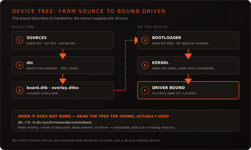
In short: The device tree describes the hardware that cannot announce itself – which is nearly everything hanging off a typical ARM SoC. It is not a configuration file where you change values until something works; it is a contract between board and driver. Reading that contract instead of guessing at it shortens a board bring-up considerably: a large share of problems that first look like driver bugs are misdescribed resources.
Why the device tree exists at all
On a PC, hardware announces itself: PCIe and USB provide identifiers from which the kernel derives the right driver. An I2C sensor on an SoC does no such thing. It sits at an address on a bus, is powered by a particular regulator, hangs off an interrupt pin – and none of that can be discovered by asking.
This description used to live as C code in the kernel, one “board file” per board. It did not scale: every hardware variant meant kernel code that had to be maintained and carried along. The device tree separates the two. The kernel provides the drivers; the device tree describes what is actually fitted on this board and how it is wired. One kernel binary can then serve many boards – a cornerstone of any maintainable embedded Linux platform.
The building blocks
The sources are text files: .dts for a specific board and .dtsi for whatever several boards share – typically the description of the SoC itself, supplied by the vendor. The dtc compiler translates them into a .dtb, a compact binary format. The bootloader loads that blob into memory and hands it to the kernel, which builds its device tree from it at startup.
Within the tree, a handful of properties carry most of the weight:
compatibleis the key. The string –"ti,tmp102", say – is matched against each driver’sof_match_table. If nothing matches, nothing happens: no error, just a device nobody serves.reggives the address: a memory address plus length for memory-mapped blocks, a bus address for I2C or SPI.interruptspoints at the interrupt controller along with a number and trigger type.clocksand regulator references describe clocking and supply – if they are missing, driver initialization aborts.pinctrldetermines which function a physical pin takes on. An SoC pin can be GPIO, I2C or PWM; without the right assignment a correctly described device sits on a pin doing something else entirely.statusarms nodes. SoC dtsi files usually define interfaces asdisabled; the board dts enables what is actually populated.
A concrete look: adding a sensor
Suppose the board carries a temperature sensor on I2C bus 1 at address 0x48, with an alert pin on a GPIO. In the board dts that reads:
&i2c1 {
    pinctrl-names = "default";
    pinctrl-0 = <&pinctrl_i2c1>;
    clock-frequency = <400000>;
    status = "okay";

    temp_sensor: temperature-sensor@48 {
        compatible = "ti,tmp102";
        reg = <0x48>;
        interrupt-parent = <&gpio2>;
        interrupts = <13 IRQ_TYPE_LEVEL_LOW>;
        #thermal-sensor-cells = <1>;
    };
};
Three details deserve attention. The bus is only brought to life by status = "okay" – the sensor node alone is not enough. The number after the @ in the node name has to match the first value of reg; if it does not, dtc warns and the tree becomes hard to read. And the pinctrl-0 reference is what makes the two SoC pins actually work as I2C rather than GPIO.
Bindings: the overlooked contract
Every compatible string has a binding document in the kernel tree under Documentation/devicetree/bindings/. It defines which properties are mandatory, which are optional and which values are allowed. Newer bindings are written as YAML schemas, which makes them machine-checkable:
make dt_binding_check   # validates the bindings themselves
make dtbs_check         # validates device trees against the bindings
These two commands save a lot of searching. They catch missing mandatory properties, typos in names and out-of-range values – exactly the class of mistake that otherwise shows up at runtime as a silent driver.
Debugging: what actually reaches the device
The most important insight during bring-up is that the source file on your workstation and the tree in the running device are two different things. Between them sit a compiler, a bootloader and possibly an overlay. The kernel exposes the tree it actually used:
# What the kernel really sees
ls /sys/firmware/devicetree/base/          # /proc/device-tree points at the same thing

# Read the running tree back into dts form
dtc -I fs -O dts /sys/firmware/devicetree/base > running.dts

# Did the driver bind?
ls /sys/bus/i2c/devices/1-0048/driver
dmesg | grep -i tmp102
If running.dts does not show the node, the problem is in the build or boot path – wrong dtb, overlay not applied, bootloader loading a stale file. If the node is there but no driver is bound, it comes down to compatible, missing resources, or the driver not being configured into the kernel at all.
Common failure patterns
| Symptom | Likely cause |
|---|---|
| Device appears nowhere, no message | status is still disabled |
| Node present, no driver bound | compatible matches no of_match_table; driver not built in |
probe aborts with -EPROBE_DEFER | A dependency is not ready – usually a clock, regulator or GPIO controller |
| Bus does not work despite correct description | pinctrl missing, or several nodes claim the same pin |
| Interrupts never arrive | Wrong interrupt-parent, wrong number or wrong trigger type |
| Sporadic errors under load | Bus clock too high, pull-ups or signal integrity – no longer purely a device tree matter |
The -EPROBE_DEFER case deserves context: it is not an error but the kernel’s regular way of postponing initialization until dependencies are ready. It only becomes a problem when it persists – then a resource really is missing.
Overlays for hardware variants
When the same base board ships in several configurations – a different display, an optional radio module – the difference can be expressed as an overlay instead of a second full dts. An overlay compiles to .dtbo and is either applied to the base tree by the bootloader or loaded at runtime:
# U-Boot: load the base tree and apply an overlay
fdt addr ${fdt_addr_r}
fdt resize 8192
fdt apply ${fdtoverlay_addr_r}
This keeps variants cleanly separated and allows the right configuration to be selected from a detected hardware identifier. The price is an extra step in the boot path that can fail in its own right – which is why a product with exactly one hardware configuration is usually better served by a single complete dts.
Maintaining device trees in a Yocto project
In a Yocto setup the board device tree belongs in your own layer, not in a locally modified copy of the kernel tree. The usual approach lists the trees to build via KERNEL_DEVICETREE and supplies your source file or patch through a kernel bbappend. The benefit shows at the next kernel jump: your description stays visible, versioned and separate from the upstream state. How we cut such layers is described under Yocto BSP & distributions; the choice of build system itself we compared in Yocto vs. Buildroot.
One last note from practice: device tree changes are cheap to make and expensive to verify. Whether all interfaces still work after an adjustment can only be confirmed reliably on real hardware – which is why we back bring-up work with automated runs on the Embedded Testrack.
Conclusion
The device tree is not a necessary evil but the place where a board explains its hardware. Treat it accordingly: read the bindings, validate with dtbs_check, compare the running tree against the source when in doubt, and keep the description in your own layer rather than the kernel tree. That removes most of the guesswork from bring-up. If a board refuses to come up or a driver stays silent, we are happy to take a look with you – device tree and kernel topics are also part of our trainings.
Frequently asked questions
- Why does my driver not probe even though the node is in the device tree?
- Three causes cover most cases. First `status`: a `disabled` inherited from a dtsi has to be explicitly set to `okay` in the board dts. Second the `compatible` string, which must match an entry in the driver's `of_match_table` exactly. Third missing resources – without the expected clocks, regulators or pinctrl entries the probe function bails out, usually with a message in dmesg.
- When is a device tree overlay worth it over a separate dts?
- Overlays pay off when the same base board ships in variants or when extensions are detected at runtime – different displays or plug-in modules, for example. For a fixed product with a single hardware configuration, one complete, versioned dts is easier to review and reason about.
- Should the device tree live in the kernel tree or in the Yocto layer?
- In your own layer. A board dts carried as a patch in the kernel recipe or as a source file in the product layer stays traceable across a kernel update, whereas changes made directly in the kernel tree get lost at the next version jump or have to be laboriously re-applied.
More on these topics
Managing Director, bitshift dynamics
Builds hardware-adjacent software for embedded products with his team – C++, Qt/QML, Embedded Linux and the Yocto Project. bitshift dynamics has worked in this field since 2005.